Materials Uncategorized

TECH BULLETIN: Moisture Problems In Floors (January 2013)

Introduction

Moisture damage is a common problem to flooring and floor structures in Florida. Vapor drive through concrete slabs often has an adverse effect on interior wood flooring. Inadequate crawlspace ventilation may lead to damage to floor structures beneath a home.

Concrete Floor Slabs on Grade

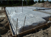
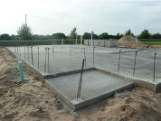
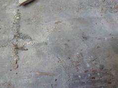
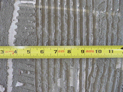
Most Florida homes are constructed with concrete slabs on backfilled soil which is also known as a slab on grade. The concrete floor slabs are typically 4″ thick with welded wire fabric for crack control. In most new homes and other buildings, the concrete floor slab on grade is placed over plastic vapor retarder. However in older buildings, this vapor retarder may not exist or is improperly placed.

In the absence of a properly installed vapor retarder, the finish flooring may be subject to moisture accumulation and moisture damage as a result of vapor drive. Vapor drive is the diffusion of moisture in the form of a gas or vapor from the soil beneath the slab through the concrete slab. If unimpeded, this moisture vapor is dispersed to the interior of the home where it is removed by the AC system. However, if an impermeable finish floor is installed on the concrete slab, the floor finish will act as a vapor retarder and trap the moisture within the floor system.

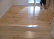
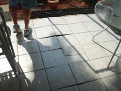
A common problem exists with the installation of modern hardwood or engineered wood flooring over older concrete slabs on grade. Modern wood flooring typically has a polyurethane finish for protection and wear, but this coating has a low permeability and can act as a vapor retarder at the top surface of the wood flooring. The polyurethane finish traps moisture from vapor drive within the wood, which can cause moisture damage to the wood flooring over a relatively short period of time.

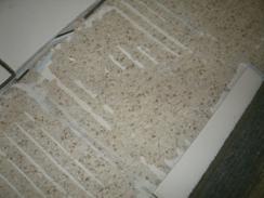
Because of vapor drive, many flooring manufacturers require that concrete slabs be tested for moisture vapor transmission rates to determine whether or not the slab is suitable for their product. Some manufacturers state in writing that all concrete slabs to receive their flooring have a minimum 6-mil poly film between the ground and the concrete to act as a vapor retarder. Unfortunately in many cases, proper testing of the concrete slab is not performed before the flooring is installed and problems with elevated vapor drive are not discovered until after the floor is installed.

A 6-mil poly film is often called a vapor barrier; however, the plastic only serves to slow or retard the moisture vapor drive and does not actually create a barrier from all moisture vapor. In floors that function well, vapor may passes through the floor and is not retained. That is why wood boardwalks along the ocean or wood balconies in the mountains may perform well for years, but wood floors inside a home may rot in a short period of time and why an unfinished wood floor over a slab on grade will perform better than one with a polyurethane coating.

Other modern floor systems are also susceptible to moisture problems due to vapor drive. These include vinyl flooring, rubber-type flooring used in medical facilities, resilient flooring used in commercial applications and gymnasiums, and area mats under chairs, which may also act as vapor barriers. Chair mats over a wood floor can leave those portions of the floor subject to elevated moisture levels and localized discoloration and rot.

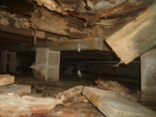
Floor Structures Over Crawlspaces

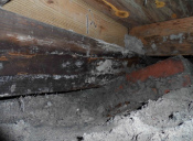
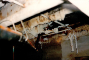
A common problem with crawlspaces is that over time, the vents in the stem walls are blocked by additions, vegetation or covered up for other reasons. The blocked vents reduce direct ventilation and cross ventilation, which leads to elevated moisture within the crawlspace. Long term exposure to high moisture can adversely affect wood, concrete, and steel structural members of the floor system. Wood may rot and/or be more susceptible to insect damage, metal trusses may corrode, and reinforced concrete may experience accelerated corrosion resulting in concrete spalling.

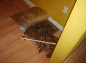
Over time as the affected floor sheathing, beams, joists, trusses, and connections deteriorate due to high moisture conditions they begin to deflect under load. This deflection may be the first noticeable manifestation of damage or a problem. If not visibly deflected, the floor may have a ‘spongy feeling’. Elevated moisture also tends to cause discoloration or stains in the wood. Other manifestations of deflection of deteriorated floor framing may include cracks or gaps in floor finish, walls, and ceilings.

Moisture damage to floor systems can also occur from condensation caused by inadequate crawlspace ventilation. Particularly during summer months, significant differentials in temperature and humidity exist between the relatively cool, dry interior air and the warm, moist exterior or crawlspace air.

Inadequate crawlspace ventilation combined with modern finish flooring can result in significant moisture problems and ultimately failure of the floor system. As with vapor drive through concrete slabs on grade, a polyurethane finish installed on modern wood flooring in an older home built over crawlspaces can act as a vapor retarder and result in condensation within the flooring system.

Condensation occurs as the relatively warm moist air in the crawlspace comes into contact with the colder underside surface of the wood floor structure, which is cooled by the air conditioning inside the home. The cold air within or near the floor system cannot hold as much moisture vapor as the warm air in the crawlspace and the moisture condenses on or within the layers of the floor structure, causing moisture damage and decay.

Summary

Water in the form of vapor drive or condensation may cause damage to finish flooring systems and floor structures. This problem is often caused or exacerbated by an inadequate moisture retarder beneath a slab on grade or insufficient crawlspace ventilation.

Materials

TECH BULLETIN: Construction Vibrations – (October 2011)

Introduction

Construction activities have the potential to cause vibrations that are perceptible to the occupants of nearby buildings. Common construction activities which cause concern are quarry and construction blasting, vibratory compaction, and pile driving. Vibrations may result in annoyance and be the suspected cause of cracking or other damages. In many cases, particularly with heavy construction in close proximity to occupied structures, documentation and monitoring should be considered prior to construction. If concerns surface after the construction is complete, the level of vibrations that occurred at a particular building can still be estimated using engineering analysis. In most cases, the determination of whether or not a certain construction activity caused particular damage can be made within a reasonable degree of engineering certainty.

General

The strength of vibrations at a given building depends upon the work performed, the proximity of the building to the vibrations, the structure of the building and the soil conditions. If the vibration energy created by the work is near and great enough, vibrations can cause building damage, typically in the form of cracks. However, the level at which vibration energy is felt by people is typically well below the vibration energy required to cause damage to a building. This often leads a building occupant to suspect that newly discovered cracks were caused by recent vibrations, when the damage may have pre-existed the vibrations.

Pre-Construction Surveys

Pre-construction surveys can play a significant role in vibration damage claims and litigation. A pre-construction survey should include the documentation of cracks and other damages in and around buildings near the intended work.

When building access is permitted, inspection and documentation of the interior and exterior should be performed. If permission to access the property is not given, photographic documentation of the building exterior from the nearest public right of way is a viable option. Seismographic monitoring is an important component of vibration analysis. If permission is granted by the building owner, the monitoring equipment should be placed adjacent to the building. Otherwise, the equipment can be placed at a distance from the work that is similar in distance and direction to the nearest building. A plot of the seismographic data is developed from which vibration strength at any given distance from the work may be predicted.

Post-Construction Investigations

The second phase of a vibration claim investigation is research into the work performed and equipment used. A visit to the work site is often helpful in conjunction with the property damage inspection. The goal is to obtain information regarding dates and nature of work, construction equipment used, pre-construction surveys if available, seismographic monitoring reports, and geotechnical reports. A written request for information is typically made to the parties responsible for the construction. Finally, after the construction data has been obtained, engineering analysis is performed to estimate the vibrations and determine the potential for damage due to direct vibrations and or settlement. The determination as to whether or not vibrations from construction activities were responsible for cracking or other damage requires the study of two mechanisms by which damage may occur. First, the direct vibrations or shaking of the structure as a result of the construction activities must be determined and compared to known thresholds for damage. Second, in the case where the structure is founded on a cohesionless soil such as sand, the potential for settlement of the structure as a result of vibrations can be approximated by rational analysis.

Closing

Vibration damage claims can be reduced by pre-construction surveys to document existing cracks and other conditions. Seismographic monitoring provides actual ground vibration experienced by nearby structures. In the absence of seismographic data, engineering analysis can be used to estimate the maximum vibrations at a given structure. The vibration data is used to determine whether the vibrations could have caused the damage.

Materials

TECH BULLETIN: Ceramic Floor Tile Bond Failure (March 2012)

Introduction

Ceramic tile is primarily composed of kiln fired clay, usually with one side glazed. Its hard surface makes it an excellent wearing surface. Ceramic floor tile in Florida is commonly installed directly to a concrete slab on grade with thinset mortar.

In order to determine the cause of a bond failure, the tile must be lifted or removed from the floor to expose the conditions between the tile and the slab. Bond failures, between the tile and thinset or between the thinset and concrete slab, are often the result of a defect with the original tile installation.

Substrate Preparation

A common cause of bond failure is an improperly prepared slab. The Handbook for Ceramic, Glass, and Stone Tile Installation published by the Tile Council of North America (TCNA) recommends that the concrete slab which is to receive ceramic tile be “…well cured, dimensionally stable, and free of cracks, waxy or oily films, and curing compounds.” We have often observed paint or other residues on slabs exposed by the removal of de-bonded tiles.

Preparing the slab should include thorough cleaning to remove all foreign materials, such as oil or paint, roughening the slab surface, and repairing existing cracks. The underside of the ceramic tile must also be rough and clean for a proper bond with the mortar. Both the TCNA and the Ceramic Tile Institute of America (CTIOA) field reports recommend concrete slabs that receive thinset mortar have steel trowel and fine broom finish. The TCNA further states “when (curing compounds) used, mechanical scarifying is necessary.” This means that for a proper bond between the mortar and the slab, the surface of the slab should be roughened and not left smooth.

Tile installed with thinset mortar directly over Terrazzo is another installation method with a high incidence of bond failure. Bond failure with this method of installation occurs because the surface of the exposed Terrazzo is very smooth.

Mortar Application

Ceramic tile bond failures also occur due to problems with the preparation and application of the thinset mortar. Problems with preparation may include an improper ratio of water in the mortar mix and re-tempering the mix by adding water after it has already begun to set. In addition, the mortar used must be compatible with the tile. Problems with application include allowing too much time between the mortar mixing and tile placement, not properly pressing or beating the tiles into the mortar, improper mortar coverage or thickness, and not allowing enough time before foot traffic or other loads are applied after installation.

The Ceramic Tile Manual lists the American National Standard Specifications for the Installation of Ceramic Tile ANSI A108.1 through 10. Within those guidelines, it is specified that the mortar should be fully distributed to the back of the tiles to achieve a minimum of 80% coverage, with 100% coverage for rib-backed tiles. The TCNA states the “average contact area for dry areas is 80% and for wet areas is 95%. Mortar coverage is to be evenly distributed to support edges and corners.”

Proper thinset mortar coverage should be achieved by pressing and beating the tiles into the mortar. A good bond requires the troweled grooves be squeezed together when the tile is pressed into the thinset. This will cause the thinset to fuse to the back of the tiles. A common defect of inadequate mortar coverage is identified when the tile is removed and the troweled grooves are readily apparent.

Structural slabs are prone to deflections under service loads and environmental effects from every day activities, such as walking, closing doors, thunder storms and other routine activities and occurrences. Over a long period of time these deflections and environmental effects will contribute to the build-up of stress between the tile and the slab, and given the conditions noted herein, may contribute to the tile bond failure. For slabs prone to deflections, the Tile Manual recommends the tile be installed over a cleavage membrane and a 1.25” to 1.5” thick reinforced mortar bed.

Properly installed tiles are water resistant and not affected by repeated exposure to water or by a single exposure to water. Tile floors are routinely washed with water. Properly installed tiles exposed to water do not experience bond failure as demonstrated by their use on exterior porches, patios, swimming pools, bathroom floors and showers. A heavy dose of water may contribute to the premature bond failure of improperly installed tiles by adding to the daily expansion and contraction stresses caused by fluctuations in temperature and humidity. These stresses may affect tiles with weak mortar bonds or those already de-bonded.

Bond failures often result in loose or tented floor tiles. Floor tiles affected in this way may not be fully supported by the underlying mortar, which increases their susceptibility to cracking due to foot traffic and other normally applied loads. Tenting is when one or more floor tiles physically lift up from the floor. It occurs due to compressive forces within the plane of de-bonded floor tile. Compressive stresses in the thinset between the floor tile and concrete slab are due to normal variations in humidity, concrete shrinkage, temperature, differences in material thicknesses and coefficients of thermal expansion between ceramic tile and concrete. If properly installed, the bond between the tile and thinset and between the thinset and concrete slab is sufficient to sustain these stresses without the tile becoming loose.

Cleavage and Isolation Membranes

Cleavage membranes and crack isolation membranes are often used in floor tile over concrete slab installations. These membranes are typically used to isolate the tile from the underlying slab and prevent discontinuity, cracking, or dimensionally instability from the slab to the tile. A crack isolation membrane is usually bonded directly to a slab with thinset mortar to adhere the tile to the membrane. A cleavage membrane is a thin layer of material that is loose laid (mechanically attached but not bonded) on the slab. When a cleavage membrane is used the mortar bed must be of sufficient thickness to sustain the differential expansion and contraction stresses between the tile and the concrete slab. Details for a cleavage membrane are shown in the Ceramic Tile Institute’s Tile Manual and specify a minimum of 1.25″ mortar bed thickness. Both the Tile Manual and the TCNA recommend reinforcing with lath or wire in the thick mortar bed. The Ceramic Tile Institute advises not to bond directly to a cleavage membrane due to the numerous failures they have observed with this system. This office has inspected numerous floor tile failures where the tile had been installed over a cleavage membrane with thinset mortar. In these cases the installation failed because the thinset was not of sufficient thickness for use with a cleavage membrane.

Summary

Bond failure with ceramic floor tiles is a common problem and often leads to loose, tented and cracked floor tiles. Installation defects, either alone or in combination, are sufficient to cause the bond to fail over time under the everyday influence of changes in temperature and humidity and minor settlement. The bond failure may start in a small area and grow with time. Compressive forces build up in the tile that would normally have been transferred to the concrete slab through shear in the thinset. These compressive forces are often relieved when the tile cracks and/or tents.